Graphics, Figures & TablesAdding "Significance Stars" to Graphs

Information and discussion about graphics, figures & tables in LaTeX documents.
Post Reply
MonsieurJoey
Posts: 3
Joined: Thu Feb 14, 2013 1:41 am

Adding "Significance Stars" to Graphs

Post by MonsieurJoey »

Hi all,

I'm having some trouble making nice graphs in LaTeX. The original graph I made in Excel looked like this.
diagram-Excel.png
diagram-Excel.png (7.67 KiB) Viewed 14682 times
But then, that's very ugly and I'd like to make one in LaTeX. Therefore, I've searched on it and then found the pgfplots package. I now made some nice bars with it.
diagram-tikZ.png
diagram-tikZ.png (16.42 KiB) Viewed 14682 times
But I cannot find an option to add the "significance stars" between some bars, which I have easily added with Paint in the Excel figure shown earlier. Can anyone help me out, perhaps with another package, by telling me how to add these stars?

Thanks in advance :)

E: The code I'm currently using for the graph:

Code: Select all

\documentclass{article}
\usepackage{babel}
\usepackage{graphicx}
\usepackage[font=small, width=0.6\columnwidth, justification=justified, singlelinecheck=false]{caption}
\usepackage{pgfplots}

\pgfplotsset{width=0.9\columnwidth}

\begin{document}

\begin{figure}[h!]
	\begin{tikzpicture}
	\begin{axis}[
	ybar,
	ymin=0,
	enlarge x limits=0.15,
	legend style={at={(0.5,-0.15)},
	anchor=north,legend columns=-1},
	ylabel={Relative intensity measured},
	symbolic x coords={PFC, BLA, DG, Ca 1, Ca 2/3},
	xtick=data,
	title={Relative calbindin expression},
	%nodes near coords,
	%nodes near coords align={vertical},
	]
		\addplot+[error bars, y dir=both, y explicit]
		coordinates {
		(PFC,8.1) +- (PFC,0.9)
		(BLA,22.6) +- (BLA,1.8)
		(DG,16.5) +- (DG,0.3)
		(Ca 1,9.6) +- (Ca 1,0.5)
		(Ca 2/3,9.8) +- (Ca 2/3,1.9)};
		\addplot+[error bars, y dir=both, y explicit]
		coordinates {
		(PFC,20.1) +- (PFC,3.5) 
		(BLA,16.1) +- (BLA,1.6)
		(DG,17.7) +- (DG,2.5)
		(Ca 1,9.8) +- (Ca 1,0.8)
		(Ca 2/3,8.8) +- (Ca 2/3,0.7)};
		%\legend{APO-SUS,APO-UNSUS}
	\end{axis}
	\end{tikzpicture}
\end{figure}

\end{document}
Thanks for the edit, localghost! I think I've added what you asked for now.
Last edited by MonsieurJoey on Thu Feb 14, 2013 7:21 pm, edited 2 times in total.

Recommended reading 2024:

LaTeXguide.org • LaTeX-Cookbook.net • TikZ.org

NEW: TikZ book now 40% off at Amazon.com for a short time.

And: Currently, Packt sells ebooks for $4.99 each if you buy 5 of their over 1000 ebooks. If you choose only a single one, $9.99. How about combining 3 LaTeX books with Python, gnuplot, mathplotlib, Matlab, ChatGPT or other AI books? Epub and PDF. Bundle (3 books, add more for higher discount): https://packt.link/MDH5p

localghost
Site Moderator
Posts: 9202
Joined: Fri Feb 02, 2007 12:06 pm

Re: Adding "Significance Stars" to Graphs

Post by localghost »

Could you upload a self-contained code example for the graph along with the corresponding data set? So it would be easier to get a clue. Files can be attached by upload to the forum server.


Best regards and welcome to the board
Thorsten
feuersaenger
Posts: 34
Joined: Sun Oct 16, 2011 5:56 pm

Adding "Significance Stars" to Graphs

Post by feuersaenger »

Hi Joey,

I am a little bit uncertain of what "significance stars" are and how they should look.

Nevertheless, the approach to "paint into the graphics" is also possible by means of pgfplots: you can place \draw, \node or \path instructions right into the axis. In order to place the graphical elements, you can rely on the "axis coordinate system"

Code: Select all

(axis cs:<x>,<y>)
.

In addition to this (very custom) form, you could use scatter plots in the same axis. Scatter plots just draw some marker at predefined places, and their color and style often comes with reasonable defaults if you write

Code: Select all

\addplot+[<your options>]
(which means to use the default styles for that plot and append your own options).

Here is what I got so far. I also took the freedom to play around with the legend:
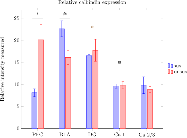
P.png
P.png (18.94 KiB) Viewed 14655 times

Code: Select all

\documentclass{article}
\usepackage{graphicx}
\usepackage[font=small, width=0.6\columnwidth, justification=justified, singlelinecheck=false]{caption}
\usepackage{pgfplots}

\pgfplotsset{width=0.9\columnwidth}

\begin{document}
\thispagestyle{empty}

\begin{figure}[h!]
		\begin{tikzpicture}
		\begin{axis}[
		ybar,
		ymin=0,
		enlarge x limits=0.15,
		legend style={at={(0.5,-0.15)},
		anchor=north,legend columns=-1},
		ylabel={Relative intensity measured},
		symbolic x coords={PFC, BLA, DG, Ca 1, Ca 2/3},
		xtick=data,
		title={Relative calbindin expression},
		%
		% --- CF:
		legend entries={sus,unsus},
		legend style={
			at={(1.02,0.5)}, anchor=west,
			draw=none,
			legend columns=1,
			nodes={anchor=west},
		},
		%nodes near coords,
		%nodes near coords align={vertical},
		]
				\addplot+[error bars, y dir=both, y explicit]
				coordinates {
				(PFC,8.1) +- (PFC,0.9)
				(BLA,22.6) +- (BLA,1.8)
				(DG,16.5) +- (DG,0.3)
				(Ca 1,9.6) +- (Ca 1,0.5)
				(Ca 2/3,9.8) +- (Ca 2/3,1.9)};
				\addplot+[error bars, y dir=both, y explicit]
				coordinates {
				(PFC,20.1) +- (PFC,3.5)
				(BLA,16.1) +- (BLA,1.6)
				(DG,17.7) +- (DG,2.5)
				(Ca 1,9.8) +- (Ca 1,0.8)
				(Ca 2/3,8.8) +- (Ca 2/3,0.7)};
				%\legend{APO-SUS,APO-UNSUS}

				% ---- CF
				\draw (axis cs:PFC,25) ++ (-10pt,0pt) -- ++(20pt,0pt);
				\node[anchor=south] at (axis cs:PFC,25) {*};

				\draw (axis cs:BLA,25) ++ (-10pt,0pt) -- ++(20pt,0pt);
				\node[anchor=south] at (axis cs:BLA,25) {\#};

				\addplot+[only marks,mark=*] 
					coordinates {(DG,23)};

				\addplot+[only marks,mark=square*] 
					coordinates {(Ca 1,15)};
		\end{axis}
		\end{tikzpicture}
\end{figure}

\end{document}
The legend options contain placement + alignment (which is explained in Section Alignment in the pgfplots manual, although it actually uses stuff from the PGF/TikZ package) and some fine tuning options to align nodes to the left. The draw=none statement is from TikZ; it disables the frame around the legend.

The drawing instructions are plain TikZ. If you want to follow the approach "paint right into the image" (which is fine), you will need to study TikZ (pgfmanual.pdf). I suppose it suffices to read part III of that manual (the part explaining TikZ); it describes path commands and nodes which is what you need here.

The scatter-plot approach using only marks is plain pgfplots, but of course, this relies on plot marks which are less customizable compared to plain graphics instructions.

Kind regards

Christian
User avatar
localghost
Site Moderator
Posts: 9202
Joined: Fri Feb 02, 2007 12:06 pm

Adding "Significance Stars" to Graphs

Post by localghost »

Oh, I was not aware of the fact that you edited your question. My approach is pretty much the same as Christian's and uses the axis coordinate system (axis cs) to place the symbols.

Code: Select all

\documentclass[11pt]{article}
\usepackage[T1]{fontenc}
\usepackage{pgfplots}

\pgfplotsset{
  compat=newest,
  xlabel near ticks,
  ylabel near ticks
}

\begin{document}
  \begin{tikzpicture}[font=\footnotesize]
    \begin{axis}[
      width=10cm,
      height=7cm,
      ybar,
      ymin=0,
      ymax=30,
      ylabel={Relative intensity measured},
      enlarge x limits=0.15,
      legend style={
        at={(0.5,-0.15)},
        anchor=north,
        legend columns=-1
      },
      symbolic x coords={PFC,BLA,DG,Ca 1,Ca 2/3},
      xtick=data,
      title={Relative calbindin expression},
%      nodes near coords,
%      nodes near coords align={vertical},
    ]
      \addplot+[error bars, y dir=both, y explicit] coordinates {
        (PFC,8.1) +- (PFC,0.9)
        (BLA,22.6) +- (BLA,1.8)
        (DG,16.5) +- (DG,0.3)
        (Ca 1,9.6) +- (Ca 1,0.5)
        (Ca 2/3,9.8) +- (Ca 2/3,1.9)
      };
      \addplot+[error bars, y dir=both, y explicit] coordinates {
        (PFC,20.1) +- (PFC,3.5)
        (BLA,16.1) +- (BLA,1.6)
        (DG,17.7) +- (DG,2.5)
        (Ca 1,9.8) +- (Ca 1,0.8)
        (Ca 2/3,8.8) +- (Ca 2/3,0.7)
      };
%      \legend{APO-SUS,APO-UNSUS}
      \draw (axis cs:PFC,27) node {\textasteriskcentered};
      \draw (axis cs:BLA,27) node {\dag};
    \end{axis}
  \end{tikzpicture}
\end{document}
Attachments
tmp.png
tmp.png (6.42 KiB) Viewed 14646 times
MonsieurJoey
Posts: 3
Joined: Thu Feb 14, 2013 1:41 am

Re: Adding "Significance Stars" to Graphs

Post by MonsieurJoey »

Thanks a lot guys, this will definitely do :)
Post Reply